UBC Formula Electric
Suspension Lead & Designer (Sep. 2024 – Present)
As the current suspension lead on UBC Formula Electric, I determined the scope of work for our 2025/26 design cycle and am currently overseeing a team of 7 members, working as a team to optimize vehicle dynamics, adjustability, and simulation of our race car. Below are highlights of the projects I’ve worked on.
1. Steering Play Reduction Project
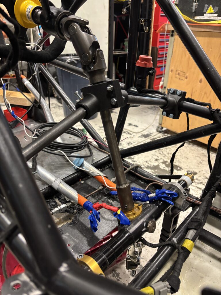
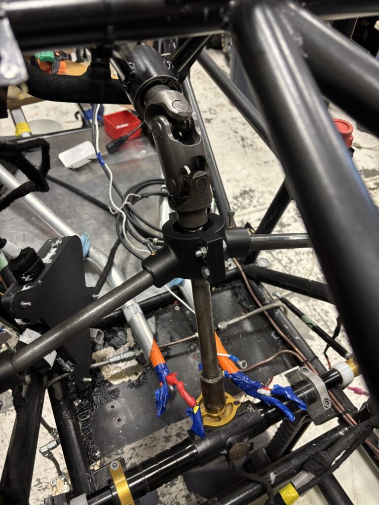
One of the main issues we had in our 2024/25 design cycle was the play we had in our steering column, allowing for significant “free play” at the steering wheel – competition rules mandate less than 7 degrees of free play. To combat this, I added an additional constraining bearing support about our double U-joint.
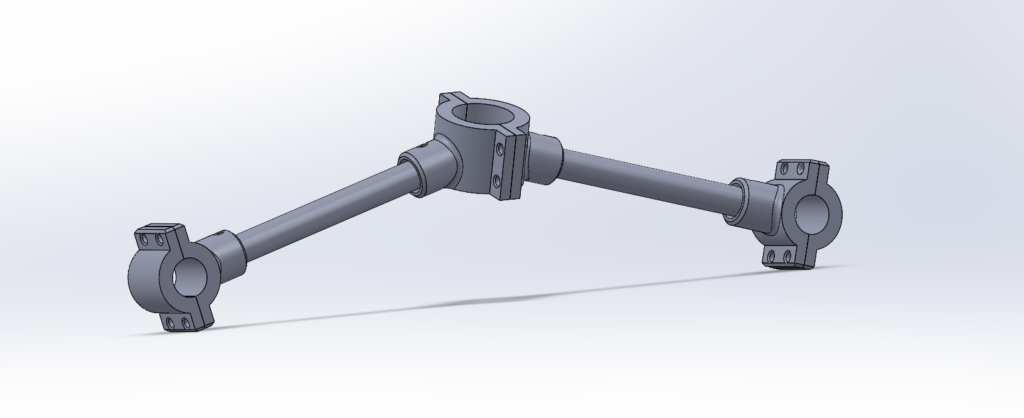
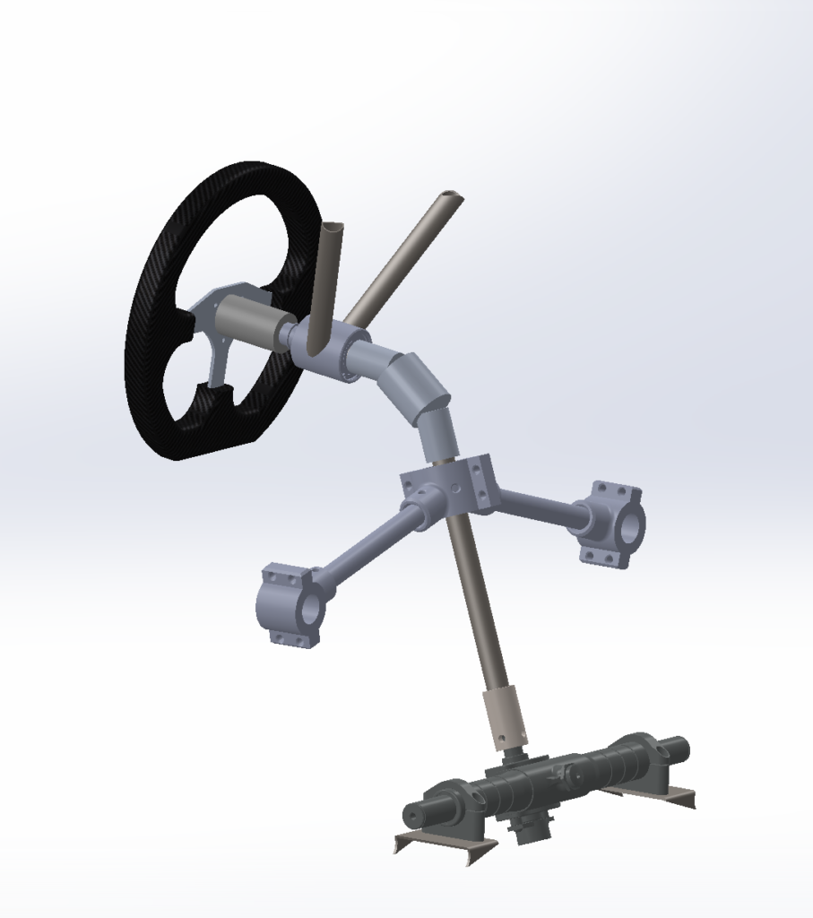
I went through stages of validation to ensure that adding the constraint would actually solve our problem and reduce the free play in the system; I was able to confirm this by using a 3D-print of the test jig above, shown below. The final design is still in-progress; a replica of the system shown below is not possible due to interference with the driver’s legs (was only used for testing the reduction in column play).
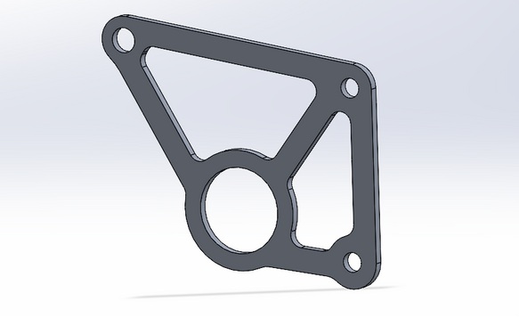
2. Bellcrank (Suspension Rocker) Design
Determined parameters for, designed, and optimized the bellcranks – a suspension rocker that connects the push rod to the shock and anti-roll bar (ARB). First, I determined the geometry of the bellcrank – the pivot arms & angles determine both the motion (leverage) ratio and linearity of the ride rate throughout travel. The geometry was constrained by two main factors:
- Wheel Travel requirements by FSAE (at least 50mm of wheel travel)
- The Resultant Damping Range (less wheel travel ideal)
From the above constraints, along with our determined optimal values for our ride frequency & spring rates, I determined the geometry and optimized the bellcranks from there. I ran multiple topology optimizations in ANSYS to optimize the strength-weight ratio based on the two different force cases this component sees, aiming for a safety factor > 2.
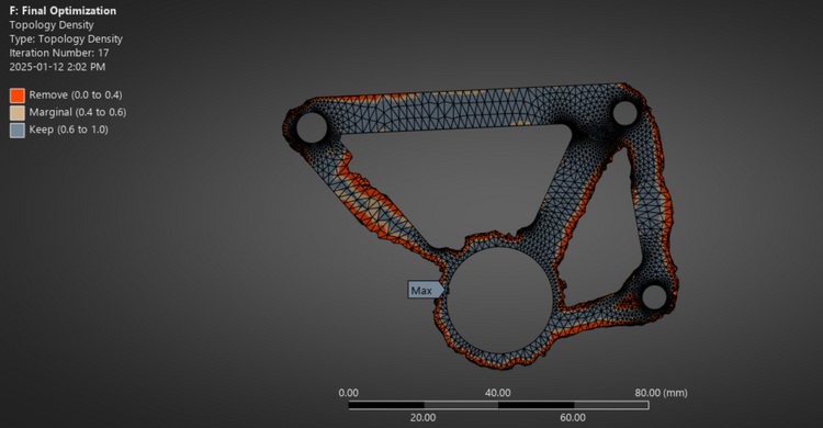
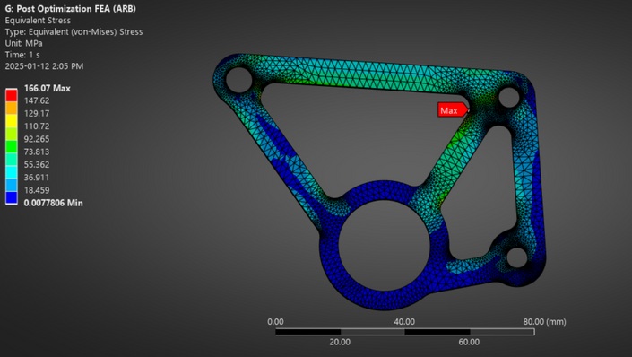
After fine-tuning the bellcrank, reducing stress concentrations resulting from the force cases, I finalized the bellcranks with an overall reduction of weight by 56.7% while increasing the safety factor from 1.5 to 2.8, also reducing cost. For my full write-up and for more information on how suspension parameters were determined, see the document linked below.
3. Suspension Tab Welding Jigs
The welding jigs are a critical component for accuracy of our suspension systems, allowing for proper fits & geometry of the intended suspension design.
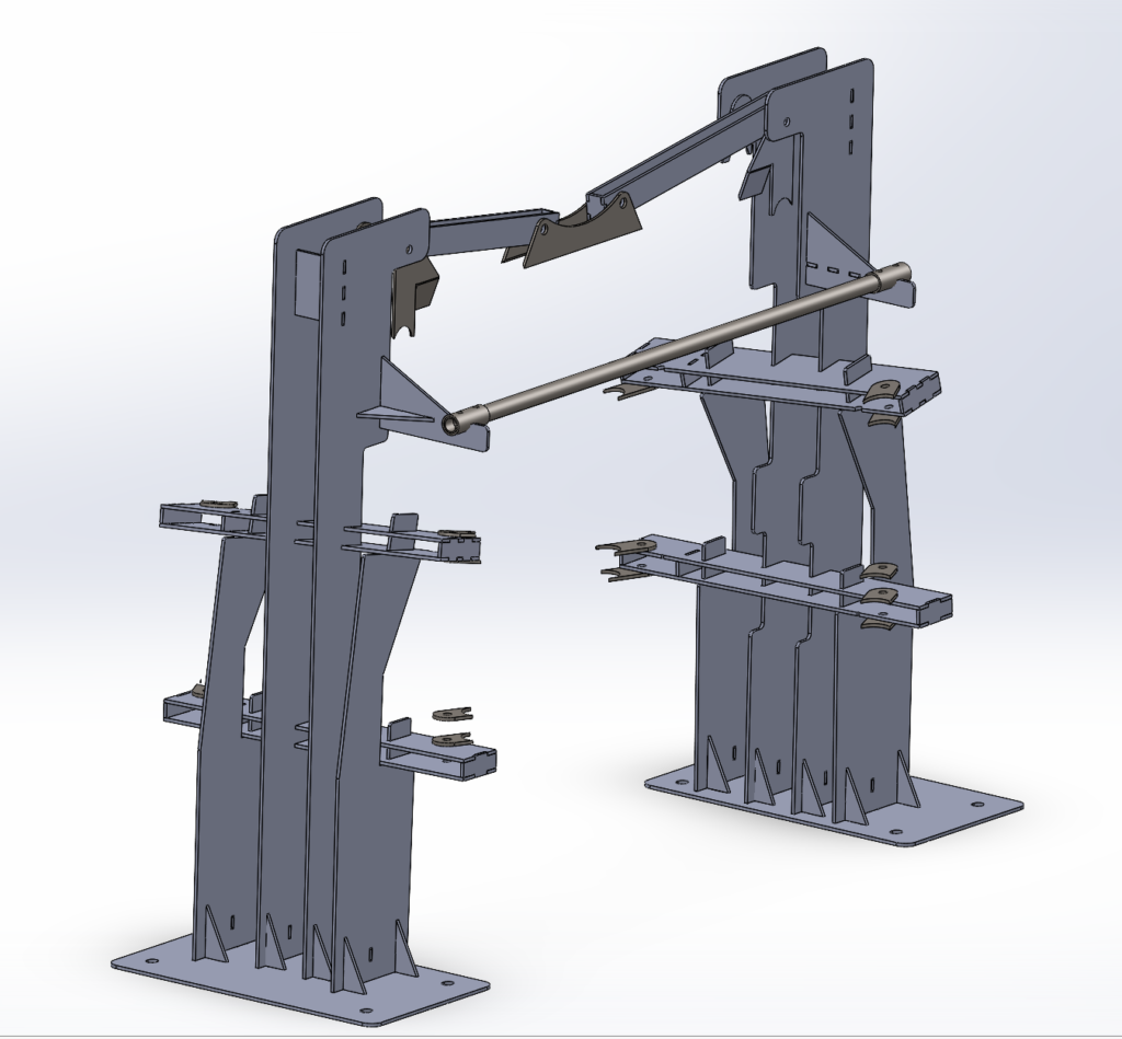
The above jig accurately locates all control arm tabs for welding on the chassis, while also allowing for the relative positions of adjacent and mirrored tabs to be correct given where the control arm tabs are located in space.
4. Suspension Member Force Script
The force-member script takes the forces seen at the wheel for different scenarios (lateral/longitudinal acceleration cases) and translates it to the suspension members. Suspension geometry is CAD derived and driven by a model in SolidWorks, which adjusts control arm / tie rod & control rod geometry based on our inputted parameters. I extended this simulation to translate the upper control arm forces to the push rod, effectively making this one simulation cover all suspension members.

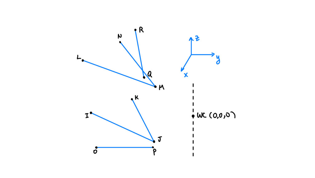
The table of loads above is the result of the simulation, showing the forces on each suspension member as a result of the geometry at each tire loading scenario – this helped in determining limiting cases & performing FEA on the members. A reference image of the suspension geometry points is also shown for context – see attached below for the full script.
Front Suspension Force Calculation
% Front Suspension Forces
% Updated 2026-Jan by AS
% Added in PR force
% Translates tire forces to upright/A-Arm forces and push rod forces

clear; clc; close all;

Points = [132.21 -340.11 -78.39
3.51	-45.35	-94.55
-140.95	-340.67	-83.46
128.21	-294.03	98.11
-9.66	-61.83	93.74
-139.35	-293.7	80.24
77	-333.6	-57.1
74.01	-50.85	-67.55
-9.66	-106.83	93.74
-9.66	-276.31	424.76
0	0	0];

WheelCenterLoads = [0.0	407.3	244.9	90.8	0.0	-4.7;
0.0	-2395.7	1715.3	-534.2	0.0	40.9;
-757.0	0.0	415.0	0.0	168.8	0.0;
1334	0	1278	0	-297.482	0;
-1455.8	-1455.8	1455.8	-324.6	324.6	44.4;
0	-2486.835	1657.89	-554.6	0.0	49.3;
-2391.2	0.0	1594.1	0.0	533.2	0.0;
0.0	0.0	2486.8	0.0	0.0	0.0;];

% Calculate pickup point x,y,z loads and push rod forces
FrontUprightLoadsTable = MemberLoads(WheelCenterLoads, Points);

% Calculate bolt loads from the table
[F_upperBoltR, F_lowerBoltR] = findBoltLoads(FrontUprightLoadsTable);

fprintf("Max upper bolt load is: %d \n", max(F_upperBoltR));
fprintf("Max lower bolt load is: %d \n", max(F_lowerBoltR));
fprintf("Max Front PR force is: %d \n", max(abs(FrontUprightLoadsTable.Push_Rod)));


function Loads = PickupPointLoads(WheelLoads, Points)

    % Points is a matrix of [x y z] coordinates representing the position of
    % suspension member from I-Q (as defined in confluence). The units are mm.

    % WheelLoads is a row vector of load applied to the wheel center in the form
    % [x y z Mx My Mz]. The units are N and Nm

    % Loads is the load exerted on the control arm and tie rod at each pickup point on the upright
    % for the loading scenario in WheelLoads. The units are N.

    % Add 0 for LCA constraint row of matrix

    WheelLoads = [WheelLoads, 0];

    b = -WheelLoads;

    % Suspension Member Points
    I = Points(1, 1:3)'./1000;
    J = Points(2, 1:3)'./1000;
    K = Points(3, 1:3)'./1000;
    L = Points(4, 1:3)'./1000;
    M = Points(5, 1:3)'./1000;
    N = Points(6, 1:3)'./1000;
    O = Points(7, 1:3)'./1000;
    P = Points(8, 1:3)'./1000;
    Q = Points(9, 1:3)'./1000;
    R = Points(10, 1:3)'./1000;
    front_wc = Points(11, 1:3)'./1000;

    % Magnitudes
    IJ = norm(I-J);
    KJ = norm(K-J);
    OP = norm(O-P);
    RQ = norm(R-Q);
    LM = norm(L-M);
    NM = norm(N-M);

    % Unit vectors (inboard - outboard)/magnitude
    ux = [1; 0; 0];
    uy = [0; 1; 0];
    uz = [0; 0; 1];
    n_IJ = (I-J)./IJ;
    n_KJ = (K-J)./KJ;
    n_OP = (O-P)./OP;
    n_RQ = (R-Q)./RQ;
    n_LM = (L-M)./LM;
    n_NM = (N-M)./NM;

    % R-vectors (from wc to inboard point)
    rP = P - front_wc;
    rM = M - front_wc;
    rJ = J - front_wc;

    % Unit Moments
    M_OP = cross(rP, n_OP);
    M_Mux = cross(rM, ux);
    M_Muy = cross(rM, uy);
    M_Muz = cross(rM, uz);
    M_Jux = cross(rJ, ux);
    M_Juy = cross(rJ, uy);
    M_Juz = cross(rJ, uz);

    % Normal vector to lower control arm plane
    n_LC = cross(n_IJ, n_KJ);

    % Force and Moment Geometry Matrices
    F_Mat = [ux, uy ,uz, ux, uy, uz, n_OP];
    M_Mat = [M_Mux, M_Muy, M_Muz, M_Jux, M_Juy, M_Juz, M_OP];
    LCA_constraint_mat = [0 0 0 n_LC' 0];

    Geometry_Mat = [F_Mat;M_Mat;LCA_constraint_mat];

    Loads = Geometry_Mat\b';

end


function LoadsTable = MemberLoads(WheelCenterLoads, Points)

    % Points is a matrix of [x y z] coordinates representing the position of
    % suspension member from I-Q (as defined in confluence). The units are mm.

    % WheelCenterLoads is a matrix of load applied to the wheel center in the form
    % [x y z Mx My Mz]. The units are N and Nm.
    % Must be in the order:
    %   1.7g Left Turn Expected LT
    %   1.7g Right Turn Expected LT
    %   1.8g Braking Expected LT
    %   1.4g Acceleration
    %   Accelerating and Right turn (1g, 1g)
    %   1.5g Right Turn full LT
    %   1.5g Braking full LT
    %   3g Bump

    % LoadsTable is a table with the load in each suspension member for each scenario
    % in WheelCenterLoads. The units are N.

    scenario = ["1.7g Left Turn Expected LT",
                "1.7g Right Turn Expected LT",
                "1.8g Braking Expected LT",
                "1.4g Acceleration",
                "Accelerating and Right turn (1g, 1g)",
                "1.5g Right Turn full LT",
                "1.5g Braking full LT",
                "3g Bump"];

    % Initialize arrays for member loads
    UCAx = zeros(size(WheelCenterLoads,1),1);
    UCAy = zeros(size(WheelCenterLoads,1),1);
    UCAz = zeros(size(WheelCenterLoads,1),1);
    LCAx = zeros(size(WheelCenterLoads,1),1);
    LCAy = zeros(size(WheelCenterLoads,1),1);
    LCAz = zeros(size(WheelCenterLoads,1),1);
    Tie_Rod = zeros(size(WheelCenterLoads,1),1);
    Push_Rod = zeros(size(WheelCenterLoads,1),1);

    % Calculate loads for each scenario
    for i = 1:size(WheelCenterLoads,1)

        MemberLoad = PickupPointLoads(WheelCenterLoads(i,:),Points);

        % Extract UCA and LCA forces
        UCAx(i) = MemberLoad(1);
        UCAy(i) = MemberLoad(2);
        UCAz(i) = MemberLoad(3);
        LCAx(i) = MemberLoad(4);
        LCAy(i) = MemberLoad(5);
        LCAz(i) = MemberLoad(6);
        Tie_Rod(i) = MemberLoad(7);

        % Calculate push rod force from UCA forces
        UCA_Forces = [UCAx(i), UCAy(i), UCAz(i)];
        Push_Rod(i) = CalculatePushRodForce(UCA_Forces, Points);

    end

    % Create output table with all member loads
    LoadsTable = table(scenario, UCAx, UCAy, UCAz, LCAx, LCAy, LCAz, Tie_Rod, Push_Rod);
end


function [F_upperBolt, F_lowerBolt] = findBoltLoads(LoadsTable)

    % Calculate resultant bolt forces in the x-y plane

    len = length(LoadsTable{1,2:end});
    F_upperBolt = zeros(len,1);
    F_lowerBolt = zeros(len,1);

    for i = 1:len
        % Upper bolt only sees forces in x-y plane
        F_bux = LoadsTable.UCAx(i);
        F_buy = LoadsTable.UCAy(i);
        F_upperBolt(i) = sqrt(F_bux^2 + F_buy^2);

        % Lower bolt only sees forces in x-y plane
        F_blx = LoadsTable.LCAx(i);
        F_bly = LoadsTable.LCAy(i);
        F_lowerBolt(i) = sqrt(F_blx^2 + F_bly^2);

    end
end


function PushRodForce = CalculatePushRodForce(UCA_Forces, Points)

    % Calculate push rod force from UCA forces using 2-force member analysis
    % UCA_Forces is a 1x3 vector [Fx, Fy, Fz] for a single load case

    % Extract suspension member points
    L = Points(4, 1:3)'./1000;
    M = Points(5, 1:3)'./1000;
    N = Points(6, 1:3)'./1000;
    Q = Points(9, 1:3)'./1000;
    R = Points(10, 1:3)'./1000;

    % Calculate magnitudes
    RQ = norm(R-Q);
    LM = norm(L-M);
    NM = norm(N-M);

    % Calculate unit vectors (inboard - outboard)/magnitude
    n_RQ = (R-Q)./RQ;
    n_LM = (L-M)./LM;
    n_NM = (N-M)./NM;

    % Two force member calculation
    % Solve: [n_RQ, n_LM, n_NM] * [T_RQ; T_LM; T_NM] = -UCA_Forces
    A = [n_RQ, n_LM, n_NM];
    T = A \ (-UCA_Forces');

    % Push rod force is the first component
    PushRodForce = T(1);
end