Custom Miniature Solenoid Valve
Custom solenoid valve designed to actuate the damping circuit on the active MTB shock. Designed & Simulated.
Problem
Need a highly responsive, electronically-controlled flow valve which regulates oil flow – for use in my Active Mountain Bike Shock personal project.
See Active Mountain Bike Shock
As a stepper motor actuated damping needle did meet requirements (with a time delay over 500ms), I set out to design and manufacture a custom solenoid valve, given commercially available solenoid valves would not be small enough.
Design
Solenoid Valve Options:
- Axial Flow vs. Perpendicular Flow Plunger
- Choice: Perpendicular to Flow – Minimizes dynamic flow forces
- Conical vs. Flat Plunger
- Choice: Conical – Minimizes air gap / travel
- Naturally Open vs. Naturally Closed
- Choice: Naturally Open – Optimal in context of the shock
Design Constraints:
- 16mm max outer diameter (to fit a 20mm OD shock stroke)
- 500+psi oil pressure flow
Initial Design:
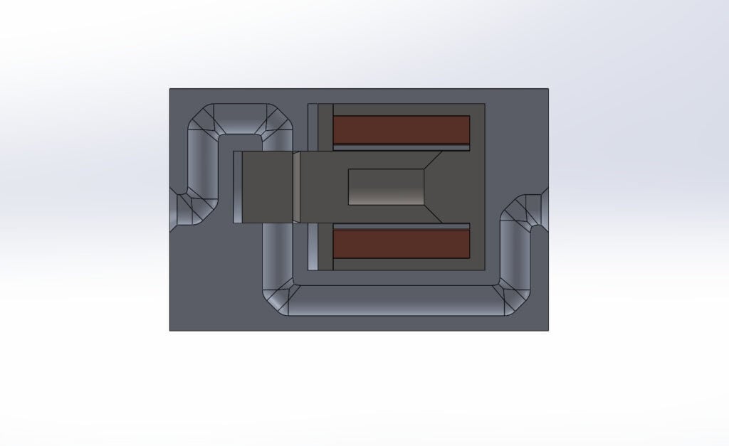
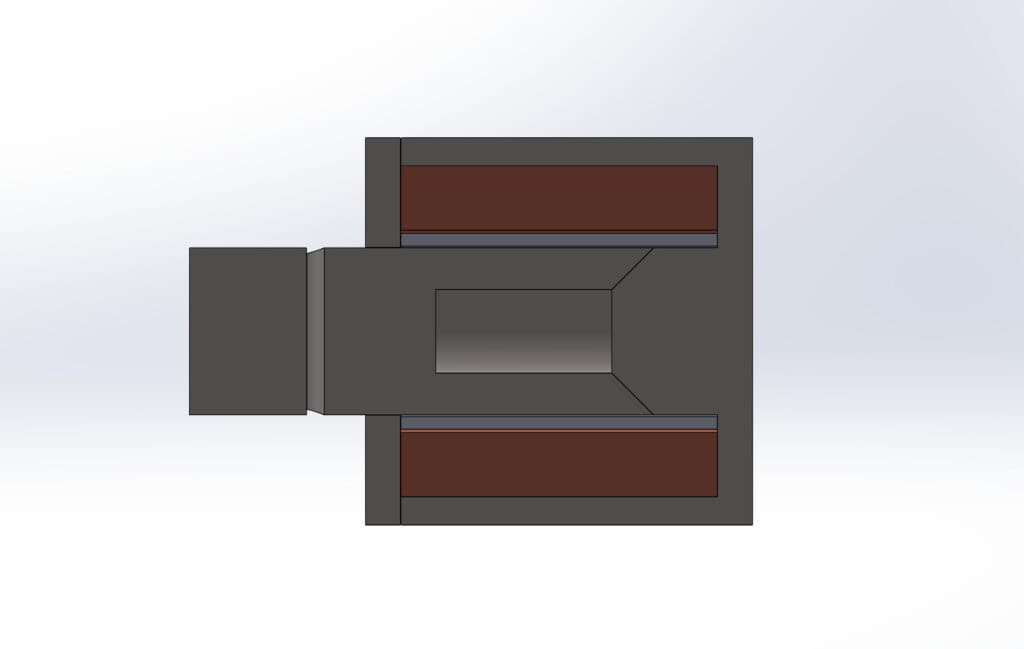
Next, I needed to validate this design and its sizing.
Hand Calculations – Magnetic & Flow forces:
This rough force calculation gives confirmation that the magnetic force should be able to overcome at least 500 psi of normal force from the oil pressure.
This is ideal, as the magnetic force should still be able to overcome the closed position spring force, while the open spring force remains larger than the oil pressure force with a decent margin.
However, due to the complex geometry of the conical plunger with a bore for the spring, I still need to validate the magnetic forces.
Magnetostatic Simulations
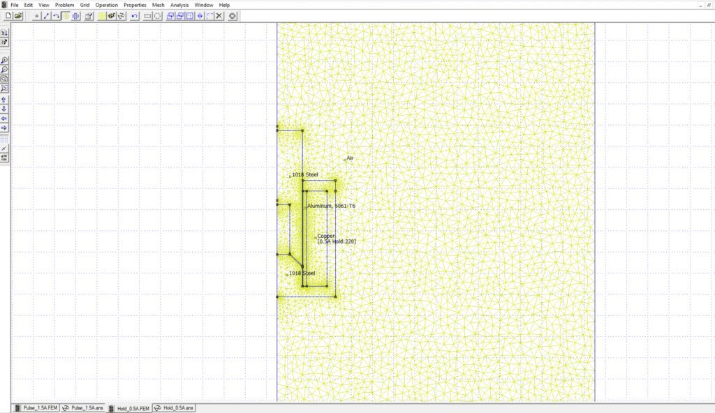
To perform the magnetostatic simulations, I used a 2D solver (FEMM) as my geometry is completely axisymmetric. Setup and mesh shown below.

After setting up, I had two force cases to validate.
- 0.5A Holding Current at a 0.1mm air gap
- 1.5A Pulse Current at a 0.5mm air gap
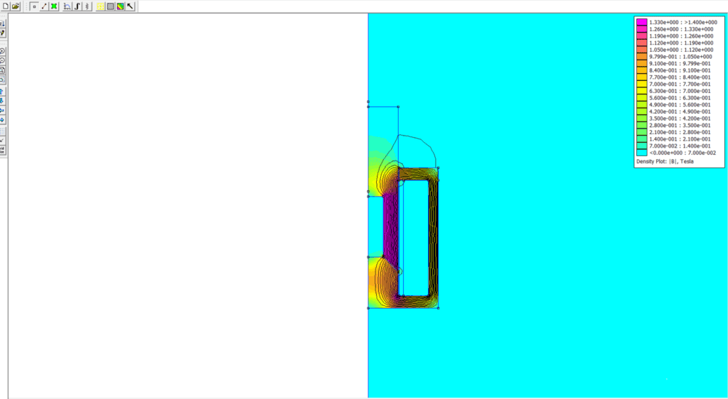
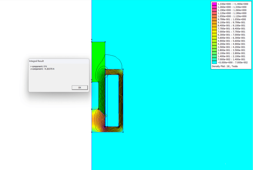
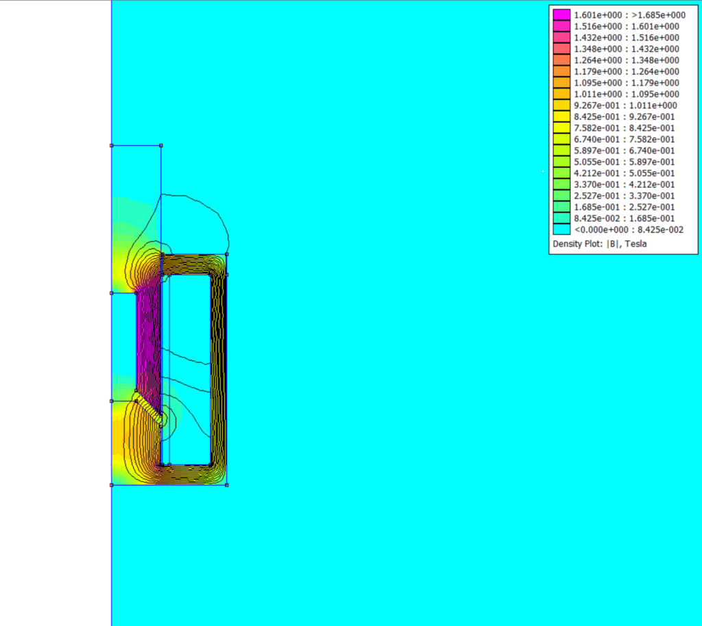
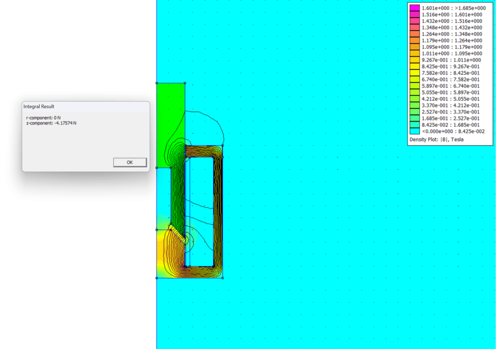
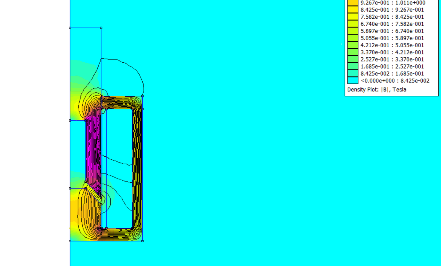
As both results lead to a plunger force of >4N, this design should work, especially given the fact that the steel spring will allow for additional flux and I could pulse the current higher than 1.5A for initial relief.
Testing, Manufacturing & Result
To be manufactured after the active mountain bike shock’s design & electronics are finalized for a prototype.