Suspension Rocker Design
Designed the rear bellcranks in SolidWorks and structurally optimized them in Ansys, cutting mass by 56.7% while raising the safety factor from 1.50 to 2.84 and reducing cost.
Overview
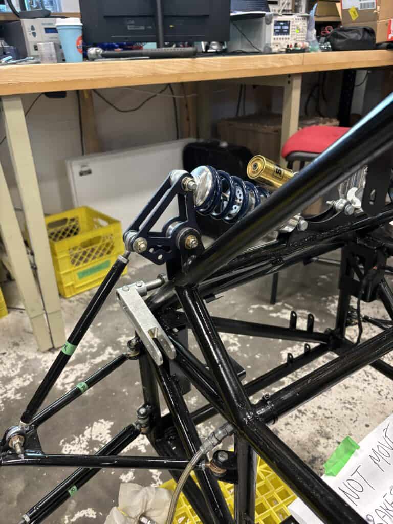
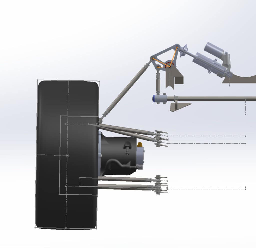
The bellcranks (suspension rockers) act as a lever arm between our push-rod (SLA suspension) and damper – this gives us control over many parameters, involving suspension rates (spring, wheel, ride), ride frequencies, damping ratios, and results of these parameters.
Our previous bellcranks used 1/2″ thick aluminum 6061 – I set out to reduce this to 1/4″ through material selection and optimization.
Geometry Optimization
Before optimizing the suspension rocker, we must determine the geometry. In short, we selected the motion ratio (leverage ratio) to satisfy the following requirements:
- >50mm wheel travel, mandated by FSAE rules
- Limits motion ratio to around 1.0 maximum (MR = damper/wheel travel)
- Front Lateral Load Transfer Distribution (FLLTD) between 48-52%
- FLLTD is a parameter based on ride and roll rates; the bellcranks are optimized in parallel with the sway bars (ARB’s) to achieve this range
- FLLTD determined based on understeer gradient behavior we want to achieve
- Competitive damping range (at least ~0.65 of critical damping)
- Higher motion ratio more optimal, as more damper travel (therefore damper speed) means more damping, F=CV
- Ride frequency around 3.0-3.5hz, rear ride frequency ~10% higher than front
- Rear rate higher than front to prevent pitching
- Not independent of FLLTD/rates.
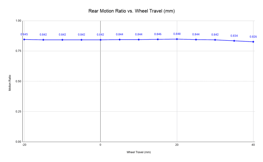
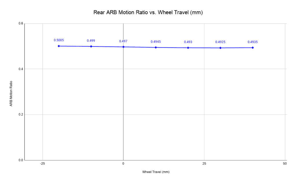
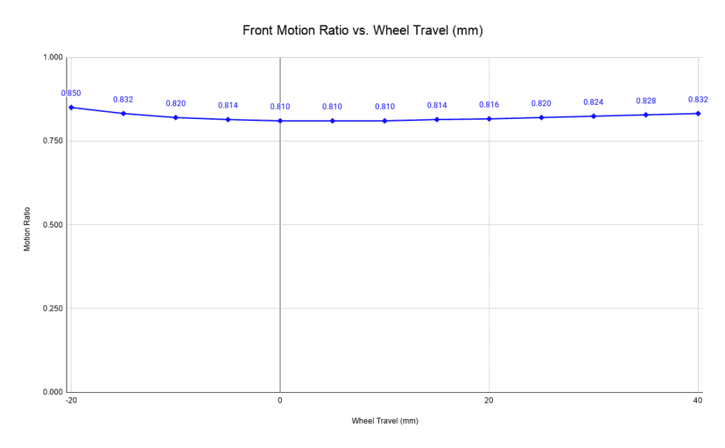
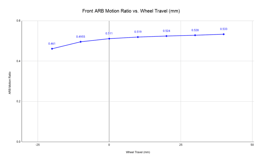
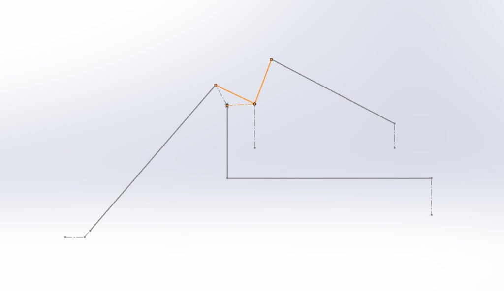
This resulted in a rear motion ratio of ~0.84 damper/wheel, which helped constrain the geometry. To reduce complexity, we decided to have this ratio linear. Below shows the parallel optimization of motion ratios I achieved for the ARB’s and bellcranks.
Which resulted in the following geometry for the rear bellcranks:
Topology Optimization
Once the geometry was locked in, we had an empty 1/8″ 7075-T6 Aluminum bellcrank plate to work with. I decided to go with 7075-T6, which has nearly double the yield strength of 6061-T6 – this allowed me to reduce the thickness from 1/4″ to 1/8″, also cutting cost as a result.
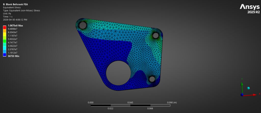
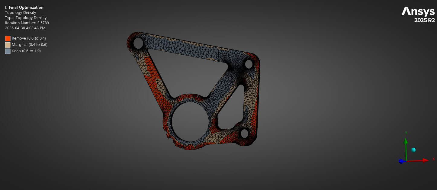
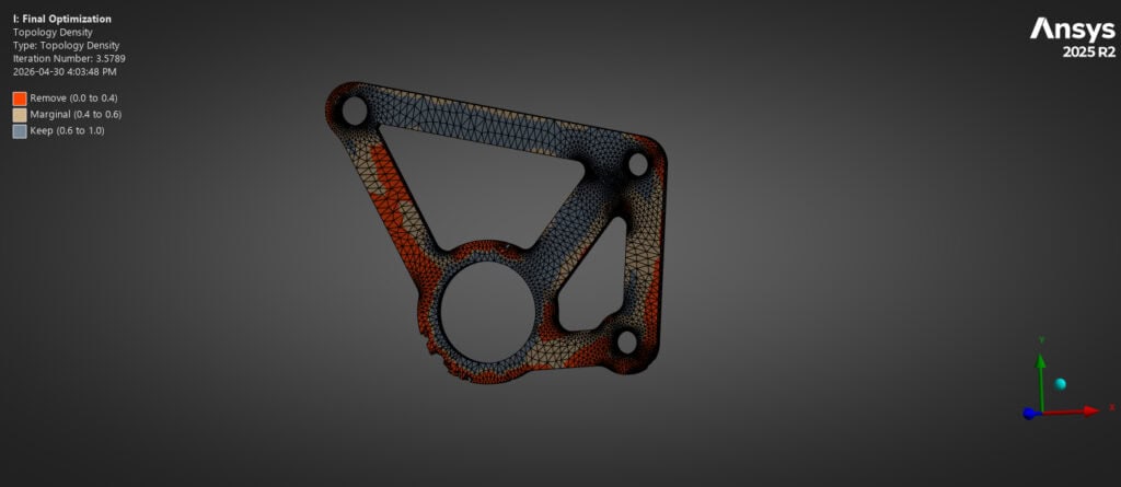
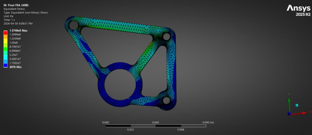
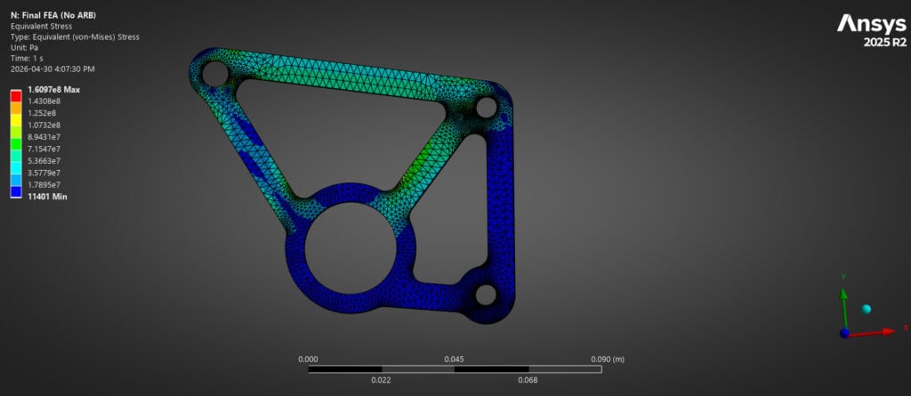
There are two force cases here (with and without sway bar, depending on if cornering or bump case), of which I ran through in multiple optimizations for both to determine the optimal cutouts.
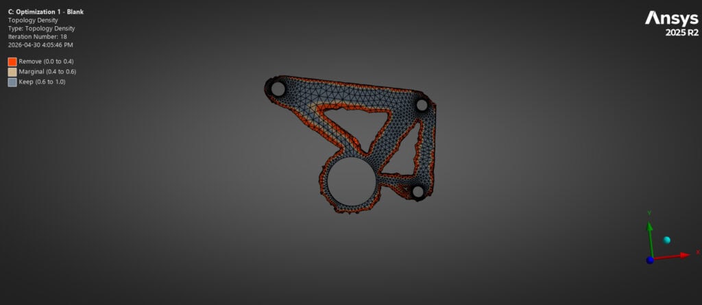
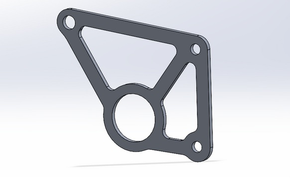
After multiple trials, I ended up with the following:
Final Design & Conclusion
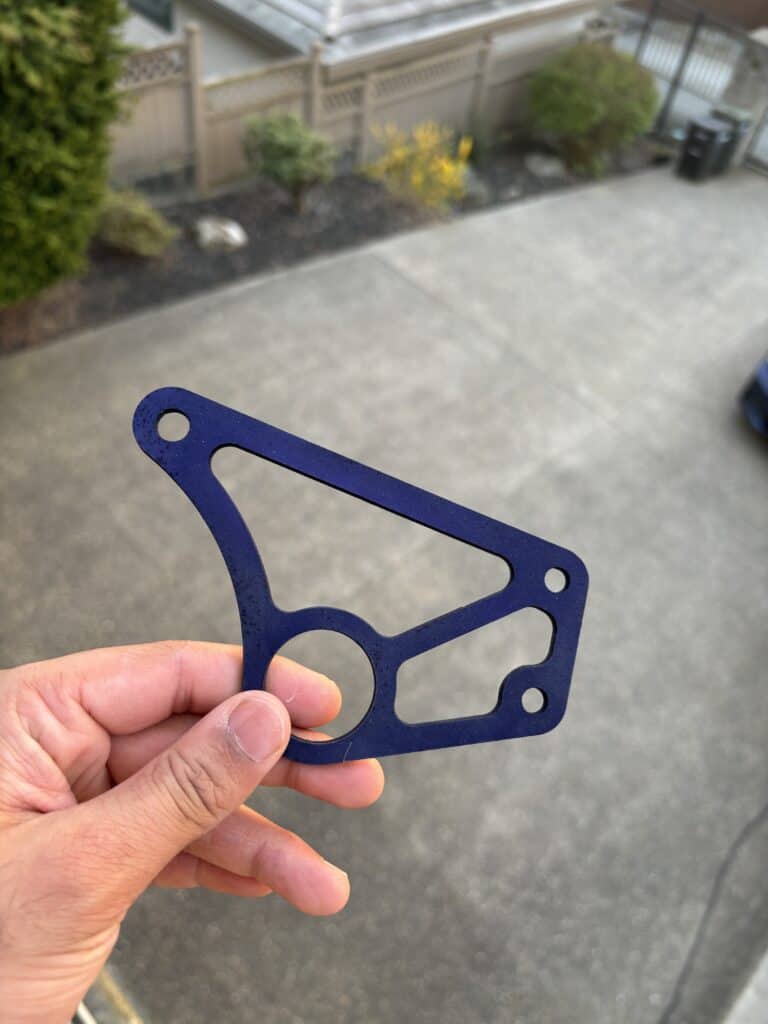
Overall, across both (maximum compression) load cases I achieved a minimum safety factor of 2.84 while reducing the mass by over 56% and reducing cost/plate waterjet.
Rear Bellcranks Final Design – Drawing