← Back to portfolio
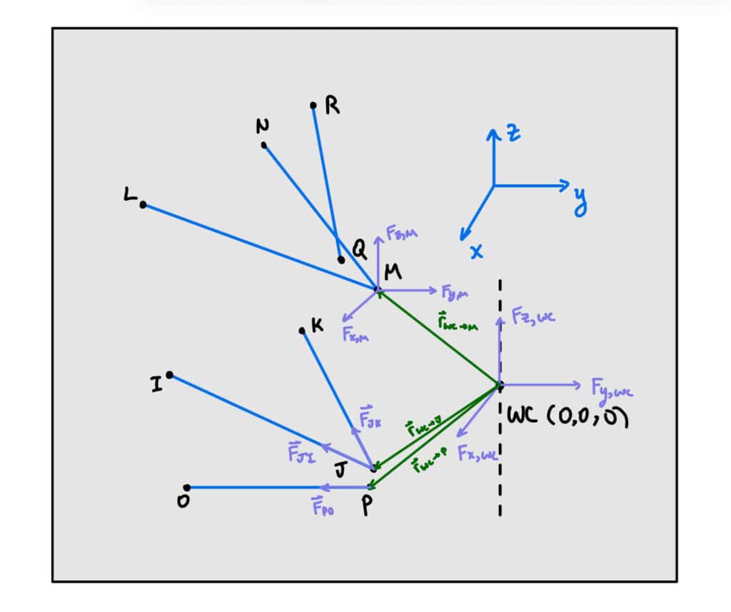
Suspension Member Force Script
Translates wheel-centre loads from various loading scenarios to forces on each suspension member.
MATLAB
Vehicle Dynamics
Load Cases
Physics of force statics shown in the image above. This script implements the force model which translates wheel centre loads to suspension members, allowing ease of changing geometry in FEA automation.
Wheel centre loads were determined from various acceleration cases (F=ma on tires, Forces & Moments translated to wheel centre).
I added the additional force translation from the upper control arm to the push rod this year – the script now provides the maximum push rod force, which I used in the bellcrank FEA and push rod calculations.
Front Suspension Forces – Script
% Front Suspension Forces
% Updated 2026-Jan by AS
% Added in PR force
% Translates tire forces to upright/A-Arm forces and push rod forces

clear; clc; close all;

Points = [132.21 -340.11 -78.39
3.51	-45.35	-94.55
-140.95	-340.67	-83.46
128.21	-294.03	98.11
-9.66	-61.83	93.74
-139.35	-293.7	80.24
77	-333.6	-57.1
74.01	-50.85	-67.55
-9.66	-106.83	93.74
-9.66	-276.31	424.76
0	0	0];

WheelCenterLoads = [0.0	407.3	244.9	90.8	0.0	-4.7;
0.0	-2395.7	1715.3	-534.2	0.0	40.9;
-757.0	0.0	415.0	0.0	168.8	0.0;
1334	0	1278	0	-297.482	0;
-1455.8	-1455.8	1455.8	-324.6	324.6	44.4;
0	-2486.835	1657.89	-554.6	0.0	49.3;
-2391.2	0.0	1594.1	0.0	533.2	0.0;
0.0	0.0	2486.8	0.0	0.0	0.0;];

% Calculate pickup point x,y,z loads and push rod forces
FrontUprightLoadsTable = MemberLoads(WheelCenterLoads, Points);

% Calculate bolt loads from the table
[F_upperBoltR, F_lowerBoltR] = findBoltLoads(FrontUprightLoadsTable);

fprintf("Max upper bolt load is: %d \n", max(F_upperBoltR));
fprintf("Max lower bolt load is: %d \n", max(F_lowerBoltR));
fprintf("Max Front PR force is: %d \n", max(abs(FrontUprightLoadsTable.Push_Rod)));


function Loads = PickupPointLoads(WheelLoads, Points)

    % Points is a matrix of [x y z] coordinates representing the position of
    % suspension member from I-Q (as defined in confluence). The units are mm.

    % WheelLoads is a row vector of load applied to the wheel center in the form
    % [x y z Mx My Mz]. The units are N and Nm

    % Loads is the load exerted on the control arm and tie rod at each pickup point on the upright
    % for the loading scenario in WheelLoads. The units are N.

    % Add 0 for LCA constraint row of matrix

    WheelLoads = [WheelLoads, 0];

    b = -WheelLoads;

    % Suspension Member Points
    I = Points(1, 1:3)'./1000;
    J = Points(2, 1:3)'./1000;
    K = Points(3, 1:3)'./1000;
    L = Points(4, 1:3)'./1000;
    M = Points(5, 1:3)'./1000;
    N = Points(6, 1:3)'./1000;
    O = Points(7, 1:3)'./1000;
    P = Points(8, 1:3)'./1000;
    Q = Points(9, 1:3)'./1000;
    R = Points(10, 1:3)'./1000;
    front_wc = Points(11, 1:3)'./1000;

    % Magnitudes
    IJ = norm(I-J);
    KJ = norm(K-J);
    OP = norm(O-P);
    RQ = norm(R-Q);
    LM = norm(L-M);
    NM = norm(N-M);

    % Unit vectors (inboard - outboard)/magnitude
    ux = [1; 0; 0];
    uy = [0; 1; 0];
    uz = [0; 0; 1];
    n_IJ = (I-J)./IJ;
    n_KJ = (K-J)./KJ;
    n_OP = (O-P)./OP;
    n_RQ = (R-Q)./RQ;
    n_LM = (L-M)./LM;
    n_NM = (N-M)./NM;

    % R-vectors (from wc to inboard point)
    rP = P - front_wc;
    rM = M - front_wc;
    rJ = J - front_wc;

    % Unit Moments
    M_OP = cross(rP, n_OP);
    M_Mux = cross(rM, ux);
    M_Muy = cross(rM, uy);
    M_Muz = cross(rM, uz);
    M_Jux = cross(rJ, ux);
    M_Juy = cross(rJ, uy);
    M_Juz = cross(rJ, uz);

    % Normal vector to lower control arm plane
    n_LC = cross(n_IJ, n_KJ);

    % Force and Moment Geometry Matrices
    F_Mat = [ux, uy ,uz, ux, uy, uz, n_OP];
    M_Mat = [M_Mux, M_Muy, M_Muz, M_Jux, M_Juy, M_Juz, M_OP];
    LCA_constraint_mat = [0 0 0 n_LC' 0];

    Geometry_Mat = [F_Mat;M_Mat;LCA_constraint_mat];

    Loads = Geometry_Mat\b';

end


function LoadsTable = MemberLoads(WheelCenterLoads, Points)

    % Points is a matrix of [x y z] coordinates representing the position of
    % suspension member from I-Q (as defined in confluence). The units are mm.

    % WheelCenterLoads is a matrix of load applied to the wheel center in the form
    % [x y z Mx My Mz]. The units are N and Nm.
    % Must be in the order:
    %   1.7g Left Turn Expected LT
    %   1.7g Right Turn Expected LT
    %   1.8g Braking Expected LT
    %   1.4g Acceleration
    %   Accelerating and Right turn (1g, 1g)
    %   1.5g Right Turn full LT
    %   1.5g Braking full LT
    %   3g Bump

    % LoadsTable is a table with the load in each suspension member for each scenario
    % in WheelCenterLoads. The units are N.

    scenario = ["1.7g Left Turn Expected LT",
                "1.7g Right Turn Expected LT",
                "1.8g Braking Expected LT",
                "1.4g Acceleration",
                "Accelerating and Right turn (1g, 1g)",
                "1.5g Right Turn full LT",
                "1.5g Braking full LT",
                "3g Bump"];

    % Initialize arrays for member loads
    UCAx = zeros(size(WheelCenterLoads,1),1);
    UCAy = zeros(size(WheelCenterLoads,1),1);
    UCAz = zeros(size(WheelCenterLoads,1),1);
    LCAx = zeros(size(WheelCenterLoads,1),1);
    LCAy = zeros(size(WheelCenterLoads,1),1);
    LCAz = zeros(size(WheelCenterLoads,1),1);
    Tie_Rod = zeros(size(WheelCenterLoads,1),1);
    Push_Rod = zeros(size(WheelCenterLoads,1),1);

    % Calculate loads for each scenario
    for i = 1:size(WheelCenterLoads,1)

        MemberLoad = PickupPointLoads(WheelCenterLoads(i,:),Points);

        % Extract UCA and LCA forces
        UCAx(i) = MemberLoad(1);
        UCAy(i) = MemberLoad(2);
        UCAz(i) = MemberLoad(3);
        LCAx(i) = MemberLoad(4);
        LCAy(i) = MemberLoad(5);
        LCAz(i) = MemberLoad(6);
        Tie_Rod(i) = MemberLoad(7);

        % Calculate push rod force from UCA forces
        UCA_Forces = [UCAx(i), UCAy(i), UCAz(i)];
        Push_Rod(i) = CalculatePushRodForce(UCA_Forces, Points);

    end

    % Create output table with all member loads
    LoadsTable = table(scenario, UCAx, UCAy, UCAz, LCAx, LCAy, LCAz, Tie_Rod, Push_Rod);
end


function [F_upperBolt, F_lowerBolt] = findBoltLoads(LoadsTable)

    % Calculate resultant bolt forces in the x-y plane

    len = length(LoadsTable{1,2:end});
    F_upperBolt = zeros(len,1);
    F_lowerBolt = zeros(len,1);

    for i = 1:len
        % Upper bolt only sees forces in x-y plane
        F_bux = LoadsTable.UCAx(i);
        F_buy = LoadsTable.UCAy(i);
        F_upperBolt(i) = sqrt(F_bux^2 + F_buy^2);

        % Lower bolt only sees forces in x-y plane
        F_blx = LoadsTable.LCAx(i);
        F_bly = LoadsTable.LCAy(i);
        F_lowerBolt(i) = sqrt(F_blx^2 + F_bly^2);

    end
end


function PushRodForce = CalculatePushRodForce(UCA_Forces, Points)

    % Calculate push rod force from UCA forces using 2-force member analysis
    % UCA_Forces is a 1x3 vector [Fx, Fy, Fz] for a single load case

    % Extract suspension member points
    L = Points(4, 1:3)'./1000;
    M = Points(5, 1:3)'./1000;
    N = Points(6, 1:3)'./1000;
    Q = Points(9, 1:3)'./1000;
    R = Points(10, 1:3)'./1000;

    % Calculate magnitudes
    RQ = norm(R-Q);
    LM = norm(L-M);
    NM = norm(N-M);

    % Calculate unit vectors (inboard - outboard)/magnitude
    n_RQ = (R-Q)./RQ;
    n_LM = (L-M)./LM;
    n_NM = (N-M)./NM;

    % Two force member calculation
    % Solve: [n_RQ, n_LM, n_NM] * [T_RQ; T_LM; T_NM] = -UCA_Forces
    A = [n_RQ, n_LM, n_NM];
    T = A \ (-UCA_Forces');

    % Push rod force is the first component
    PushRodForce = T(1);
end